Adaptive Meshing and Computational Fluid Dynamics
When it comes to high-thrust applications, solid rocket motors provide the best performance at the lowest cost. The U.S. Department of Defense, NASA, and an ever-growing private industry depend on solid rocket motors to get people and payloads where they need to go, with applications ranging from ejection seats on fighter jets to boosters on launch vehicles. Scientists and engineers at Illinois Rocstar use Rocstar Multiphysics™, a suite of simulation software designed for highly complex, highly energetic scenarios. Rocstar Multiphysics™ enables users to mix and match simulation codes for different physical domains to suit a wide range of engineering applications, bringing together tools for mesh generation, computational structural mechanics, computational fluid dynamics, combustion modeling, data management, post-processing, and visualization.
In a commercial application, Rocstar Multiphysics™ was used to model an Attitude Control Motor (ACM). The ACM is a small solid rocket motor consisting of a titanium alloy case, phenolic composite nozzle, and ammonium perchlorate composite propellant (APCP). Arrays of these motors are mounted on larger rockets and used to control the orientation or “attitude” of a missile in the final moments before impact. Specifications and performance data for the ACM were provided by Atlantic Research Corporation (now part of Aerojet Rocketdyne). Illinois Rocstar combined modules for adaptive meshing, computational fluid dynamics, and combustion mechanics into a system designed for modeling the internal ballistics of the solid rocket motor.
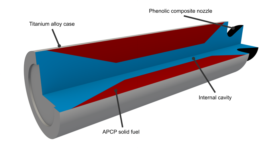
A cut-away view of the ACM is shown in Figure 1. Combustion occurs within the fluid domain (blue), representing the air-filled cavity at the center of the rocket. As the solid propellant (red) burns away, the fluid domain expands until it reaches the boundaries of the motor case (gray). Modeling the movement or “burnback” of the fluid/solid interface is challenging but critical for obtaining an accurate estimate of motor performance.

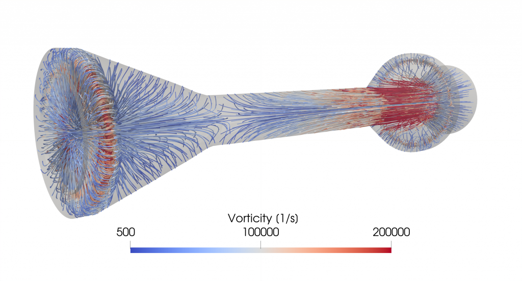
Our simulation of the ACM in Rocstar Multiphysics™ begins immediately following ignition, shown in Figure 2. Within milliseconds, the motor develops temperatures in excess of 3000 °C and pressures in excess of 60 megapascals. As the propellant regresses, the Rocstar Multiphysics™ meshing module continuously adjusts the mesh to track the burning surface. Approximately 12 milliseconds into the simulation, all of the propellant is consumed, the rocket burns out, and temperature and pressure return to ambient.

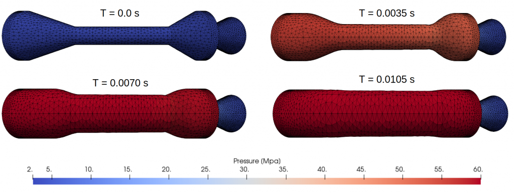
In each instance, the visualization shows the interface between the solid fuel and the hot gas in the combustion chamber, shown in Figure 3. At 0 seconds, the fuel surface has not been ignited and pressure is constant. Following ignition, pressure begins to build in the motor, starting in the converging head section. The transitions between the conical end sections and the tubular middle section become rounded as the sharp corners are burnt away. At 0.0070 seconds, the conical end sections have stopped moving while the tubular middle section continues to expand. Most of the fuel has been consumed at t = 0.0105 seconds and the fluid domain has almost reached the case boundary.

We note that movement of the fluid/solid interface is determined by the linear burn rate, which is fully coupled to flow properties. The Illinois Rocstar Promesh™ adaptive meshing technology, implemented within the Rocstar Multiphysics™ meshing module, updates the fluid domain to match the regressing interface and iteratively smooths both surface and volume meshes to improve solution accuracy. The ability to track moving boundaries and effectively propagate mesh changes is unique to Rocstar Multiphysics™ and a key technology for modeling time-dependent internal ballistics in solid rocket motors.
Whether for rockets, wind turbines or hypersonic vehicles, Rocstar Multiphysics™ has the simulation capabilities to fit user needs. With a 25-year academic and commercial legacy that has been thoroughly modernized for the 21st century, Rocstar Multiphysics™ integrates a diverse portfolio of tools for mesh generation, computational structural mechanics, computational fluid dynamics, combustion modeling, and more. Contact the Illinois Rocstar team today at rocstar@illinoisrocstar.com to see how Rocstar Multiphysics™ can solve your engineering problem.


